Vehicle Control Unit
I spent the summer of 2023 at Jacobi Motors, LLC, a company innovating electric motor design. The main project that summer was converting a diesel tractor to an electric vehicle using their novel motor.
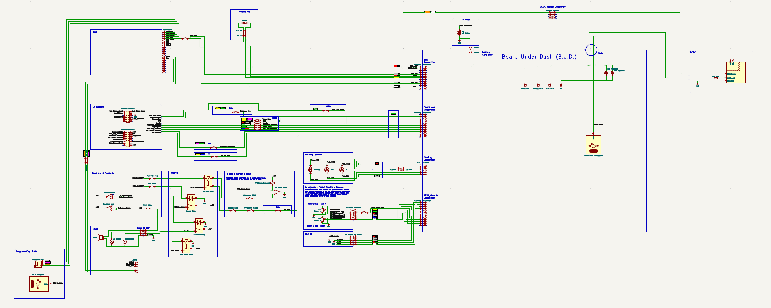
My first task was reverse engineering the tractor's wire harness to integrate its existing electronics like the lights, the dashboard, and the driver controls with the added inverter, battery, and cooling systems. Here's the schematic.

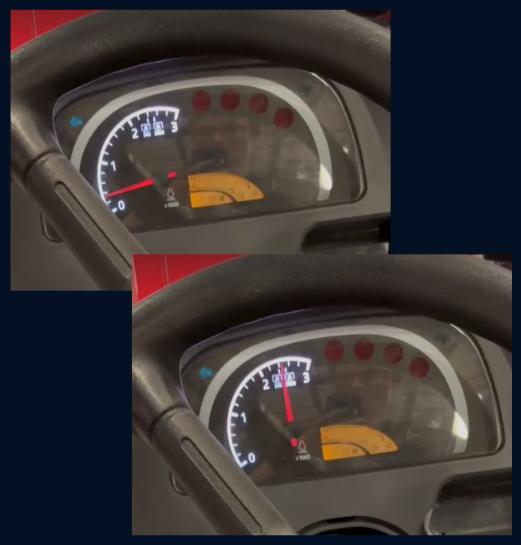
I was able to reverse engineer the tractor's dashboard, which saved lots of company time and money spent on developing a new one. Pictured below is the stock tachometer hijacked by my PCB after I discovered it used pulse-frequency modulation.

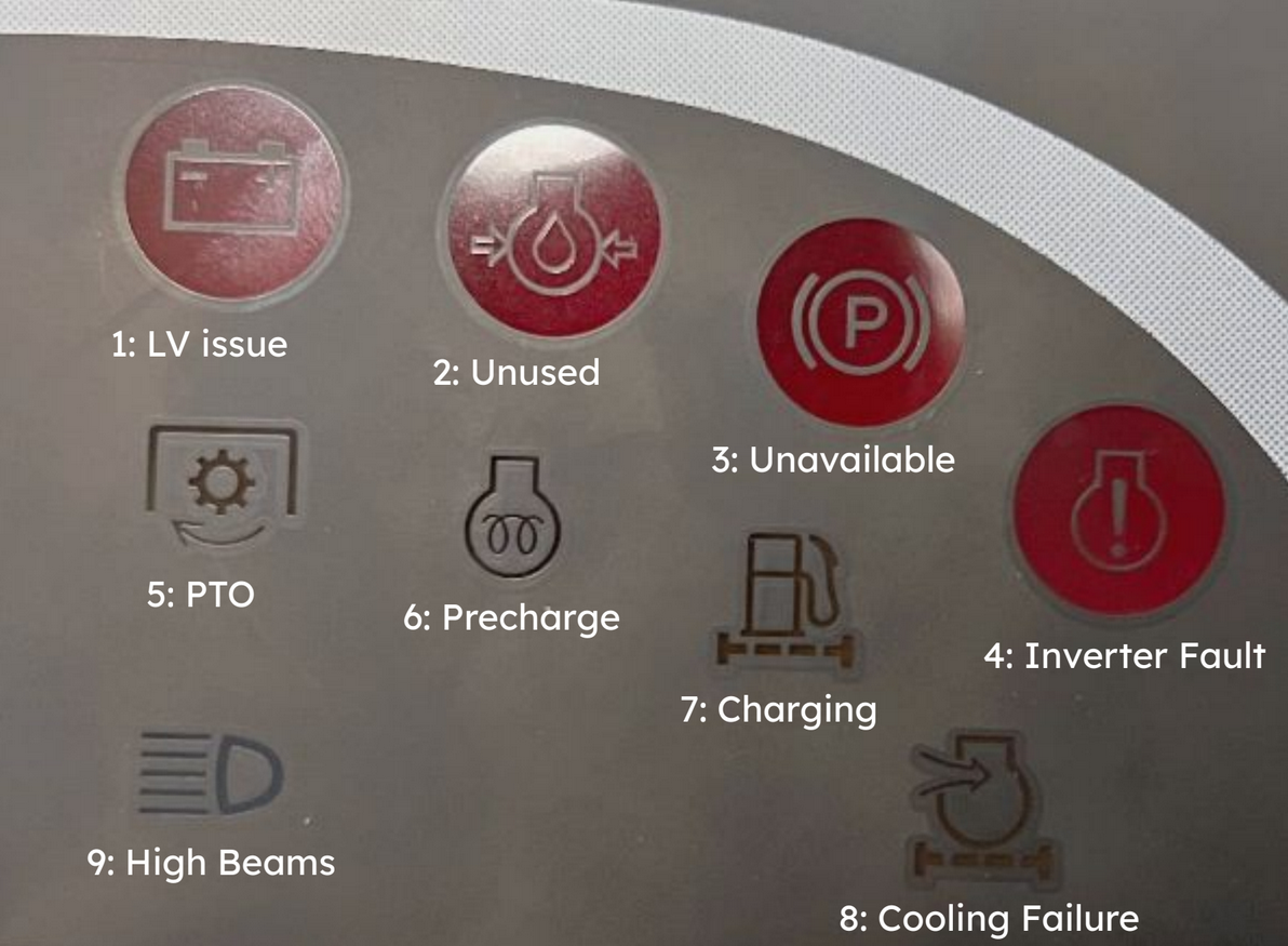
I also gave the indicator lights on the dashboard new meanings. For example, the check engine light is now the inverter fault light.

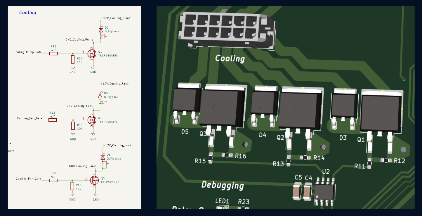
Once I understood the tractor's electronics, I had to design a PCB to interface between them and the inverter, BMS, and cooling. This board effectively became a Vehicle Control Unit. It had to respond to driver controls like turning the key and pressing the pedal with contactor sequences and inverter torque requests. It also ran closed-loop cooling.

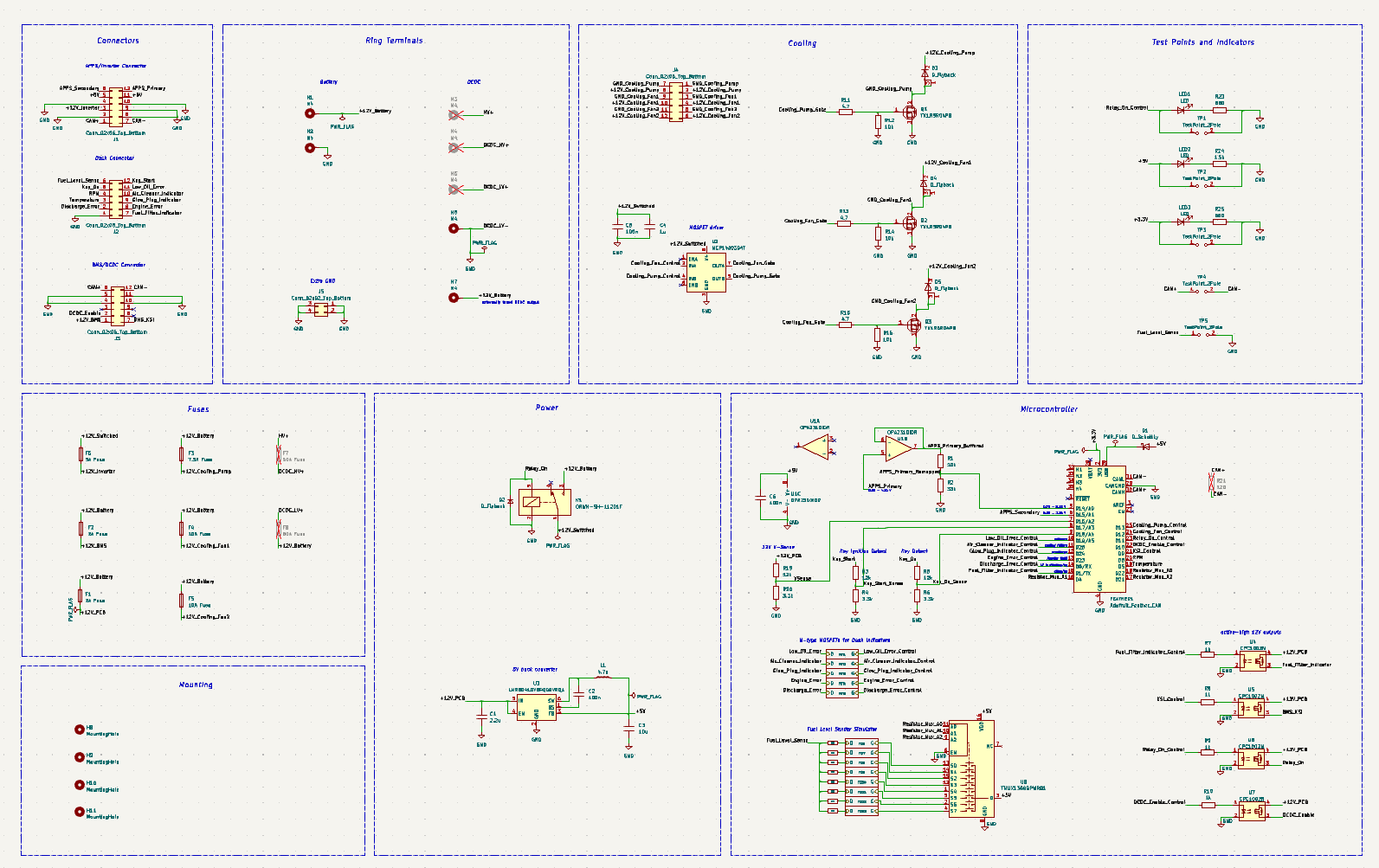

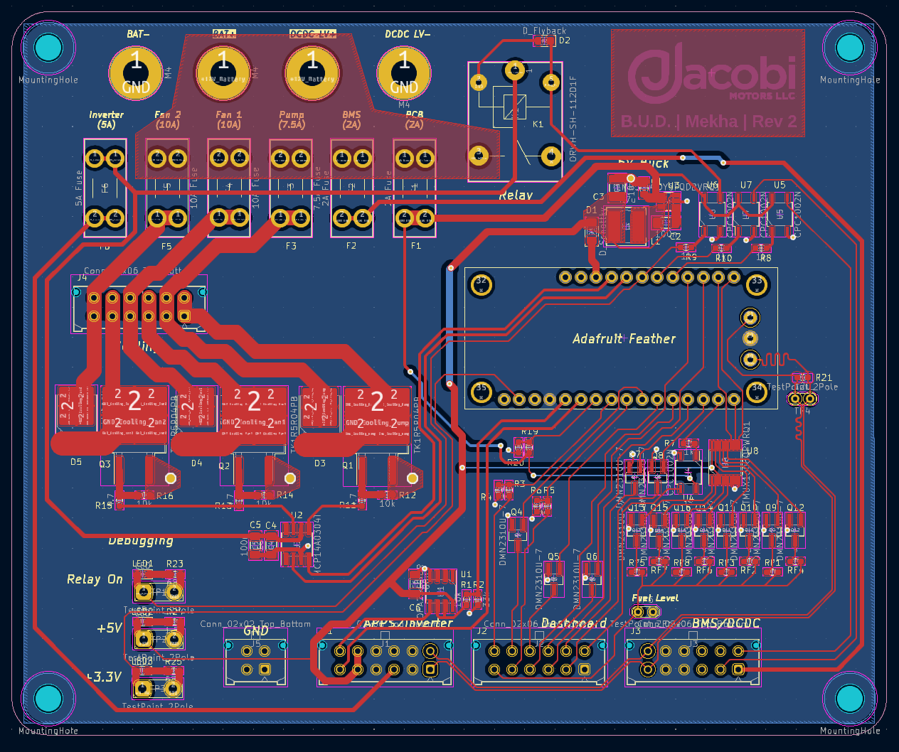

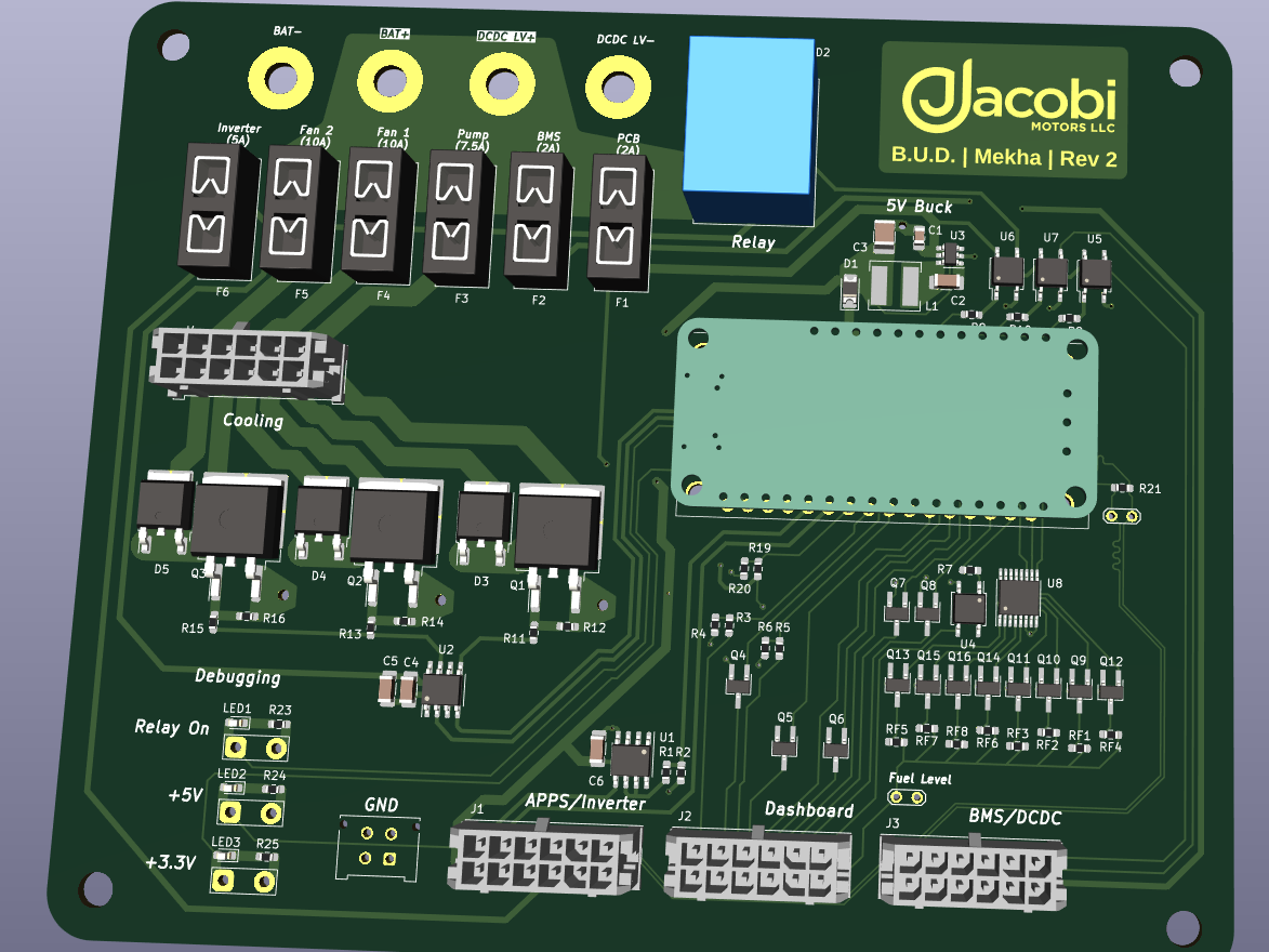
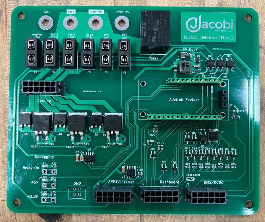
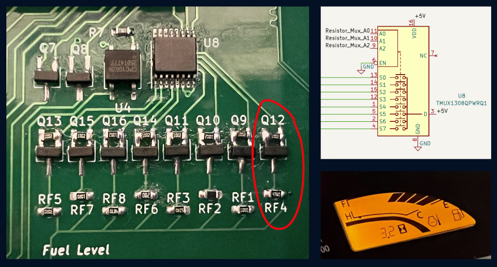
There are some interesting design decisions I wanted to highlight. To display the battery's state of charge on the dashboard, I needed to emulate the previous fuel gauge potentiometer. The fuel gauge only had 8 notches though, so I decided to use 3 IO pins on the microcontroller as well as a Texas Instruments multiplexer IC to select 1 of 8 resistors, where each resistor corresponds to a certain number of fuel notches on the dashboard.

For the cooling system, I used a N-type MOSFETs and a driver IC to control the pump and fans with a variable duty cycle for closed-loop control. I laid out high-current traces with enough width such that the temperature delta would be acceptable. I also made it a requirement that the MOSFETs could handle switching frequencies outside the audible range of human hearing, and I ended up running them at around 30 kHz to avoid an unpleasant buzzing noise.

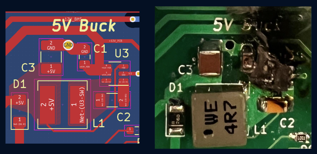
To drop the 13-14V from the battery to 5V, I used a Texas Instruments buck converter IC with a layout that minimized switching loop parasitic inductance. It worked great for a couple weeks until I touched it during operation (aftermath pictured below on the right).

The firmware for the board involved making a state machine and some drivers for analog voltage reads and CAN communication.

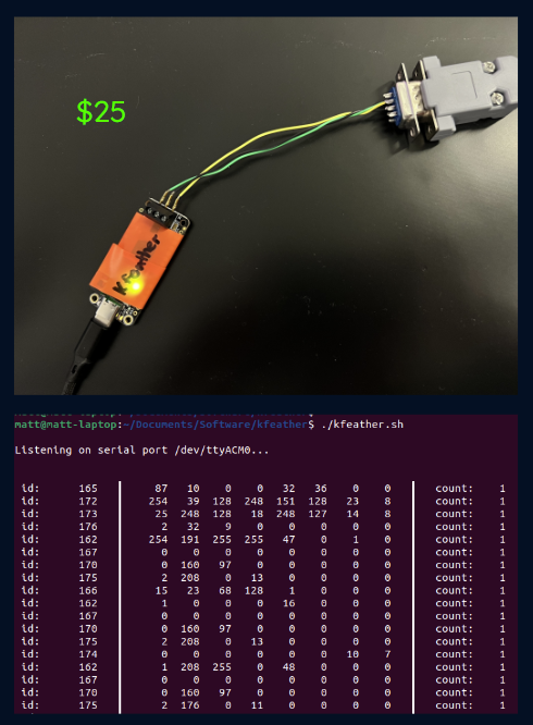
With one of the spare microcontrollers, I made a Kvaser clone that relayed CAN data over USB, and I made software in Python to take the stream of packets from USB and output them to the Linux terminal. Each microcontroller costs $25, while a Kvaser leaf costs over $300.
Because I was only there for a summer, I made sure to document all of my work, and as far as I know, the PCB still works!